Hydraulic Cylinder Applications in Dump Trailers and Tipper Trucks: A Sizing Guide
Sizing a hydraulic cylinder for a dump trailer or tipper truck is a geometry exercise, not a catalog lookup. A front-end telescopic cylinder, an underbody telescopic cylinder and an inverted front-mount telescopic cylinder can all raise the same body, but they install in different places, demand different structural support and convert pressure into lift at different points in the tipping arc. This guide explains what each configuration is, which inputs actually decide the size, and how to verify a selection before a purchase order is issued.
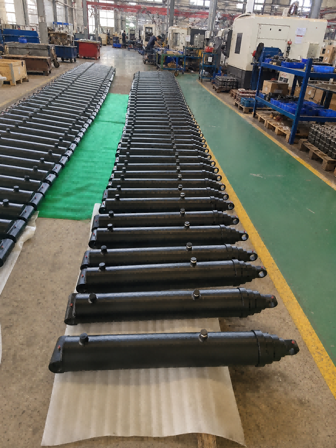
Single-acting multi-stage telescopic cylinders are the workhorse configuration for dump body and tipper lifting duties.
Why Dump Trailer and Tipper Cylinder Sizing Goes Wrong
A tipping cylinder is often chosen from a capacity column, and that is the first mistake. A published rating describes a specific assembly under defined installation geometry; it is not the same as trailer payload capacity. In scissor hoist selection, for example, the final result depends on dump body length, rear overhang, hinge location, desired dump angle, hoist mounting position, hydraulic pressure, trailer GVWR, axle rating, tire rating and frame strength. A unit that looks adequate on paper can be marginal in service because the geometry, not the number, decides the outcome.
The second mistake is treating stroke as the answer to dump angle. On a multi-stage telescopic cylinder, the maximum dump or lift angle is determined by equipment geometry rather than by cylinder stroke alone. Stroke, hinge position and cylinder base position form one set of dimensions and have to be evaluated together. The remaining failures follow the same pattern:
- Retracted length ignored. Telescopic construction exists to provide a long working stroke from a compact retracted envelope. Retracted length is what actually fits between the trailer frame and the body, and it is commonly the binding constraint.
- Return method mismatched. A single-acting cylinder returns by gravity, external load, spring force or mechanical linkage, and the minimum return load is defined by seal friction, guide friction and installation orientation.
- Stage force distribution ignored. Initial lifting force is calculated from the effective area of the largest stage. Each subsequent stage has its own output force, and the load curve must be evaluated through the complete tipping cycle.
- Side loading unmanaged. Telescopic cylinders must be protected from excessive side loading, and horizontal or inclined installations require individual engineering review.
- Flow and port size underestimated. Hydraulic flow requirement is calculated from cylinder displacement and the required cycle time, and port size is selected accordingly.
Typical selection inputs: original cylinder model number; 10-digit part number; number of stages; stroke length; closed length; base and rod-end pin diameters; mounting widths; hydraulic port size and position; dump body length; body hinge-to-cylinder base distance; rated payload; required dump angle; system working pressure; installation photographs or drawing.
Industry Background: A Growing Telescopic Segment
The global hydraulic cylinder market was valued at USD 15.7 billion in 2024 and is projected to reach USD 24.7 billion by 2034 (Global Market Insights). Within that market, the telescopic cylinder segment generated USD 2,225.1 million in 2024 with a projected CAGR of 5.9% (Grand View Research). That segment is driven in part by tipping and lifting equipment, where a long working stroke has to fit inside a short installation space.
Demand is concentrated in mobile machinery. Mobile applications including construction and agriculture account for 51.8% of hydraulic cylinder demand (Grand View Research). By construction type, welded cylinders held a dominant 53.6% share in 2025 because of durability in heavy-duty applications, while tie-rod cylinders accounted for approximately 38.9% of the product type segment (Future Market Insights). Double-acting cylinders dominate the function segment with a 71.6% revenue share as of 2025 (Grand View Research) — worth remembering when sizing a tipping cylinder, because dump body lifting remains a predominantly single-acting, gravity-return duty in the configurations described below. Bore sizes up to 150 mm held the largest share at 61.6% in 2025.
Supply is centered on Asia Pacific, which commanded a 40.5% revenue share in 2025, led by China and India. China's hydraulic cylinder and systems exports have grown at roughly 11.5% CAGR (IndexBox), and the average export price for hydraulic cylinders and systems stood at approximately USD 382 per unit in 2024 (IndexBox). In North America, the U.S. hydraulic cylinder market is projected to reach USD 3.31 billion by 2032 on infrastructure modernization (Fortune Business Insights). Customization and OEM services are identified as a growing segment as industries shift toward specialized machinery (Market Research Future).
Three standards are frequently referenced when buyers compare mounting dimensions. ISO 6022:2006 establishes the mounting dimensions for single rod hydraulic cylinders in the 250 bar series to ensure interchangeability. ISO 6020-2:2015 specifies mounting dimensions for the 160 bar series compact cylinders. NFPA/T3.6.7 R3-2009 (R2024) is the industry standard for square head industrial cylinder mounting dimensions in North America. These standards govern stationary and industrial cylinder families; mobile tipping cylinders are dimensioned around the vehicle installation envelope instead, which is why a replacement selection is normally confirmed against pin-to-pin dimensions, pin diameters, mounting widths and port position.
The Configurations That Do the Lifting
Front-End Telescopic Cylinders (FC, FE and FEE Alpha Series)
A front-end telescopic cylinder is mounted at the front of the tipper body and raises the body toward a rear hinge. The reference range covers 3–6 stages, a first-stage effective diameter of 118–191 mm, and both standard-duty and heavy-duty configurations with standard or hard-chromed stage options.
Stroke and capacity scale with the family. In the reference FC range, listed strokes run from 3,880 to 8,130 mm and listed lifting capacities from 33 to 79 metric tons, with oil volumes of 34–134 L and unit weights of 190–405 kg. The FE range covers listed strokes of 3,880–7,130 mm, capacities of 30–61 metric tons, oil volumes of 41–139 L and weights of 142–316 kg. The FEE family covers 4,165–6,150 mm in the representative models listed, within a broader family stroke range of approximately 2,785–9,030 mm depending on model. Across the complete front-end catalog, capacity spans 5–100 metric tons. Maximum working pressure is up to 250 bar, with typical model-dependent values between 170 and 250 bar.
Body connection distinguishes the three families: FC uses a cover-type or trunnion-type arrangement, FE uses an eye-type front-end mounting, and FEE uses a piston eye and bottom eye with pin. Mounting brackets are supplied in maintenance-free or greased configurations. All of these are single-acting cylinders with gravity and tipper-body load return, so retraction depends on the descending body rather than on hydraulic power.
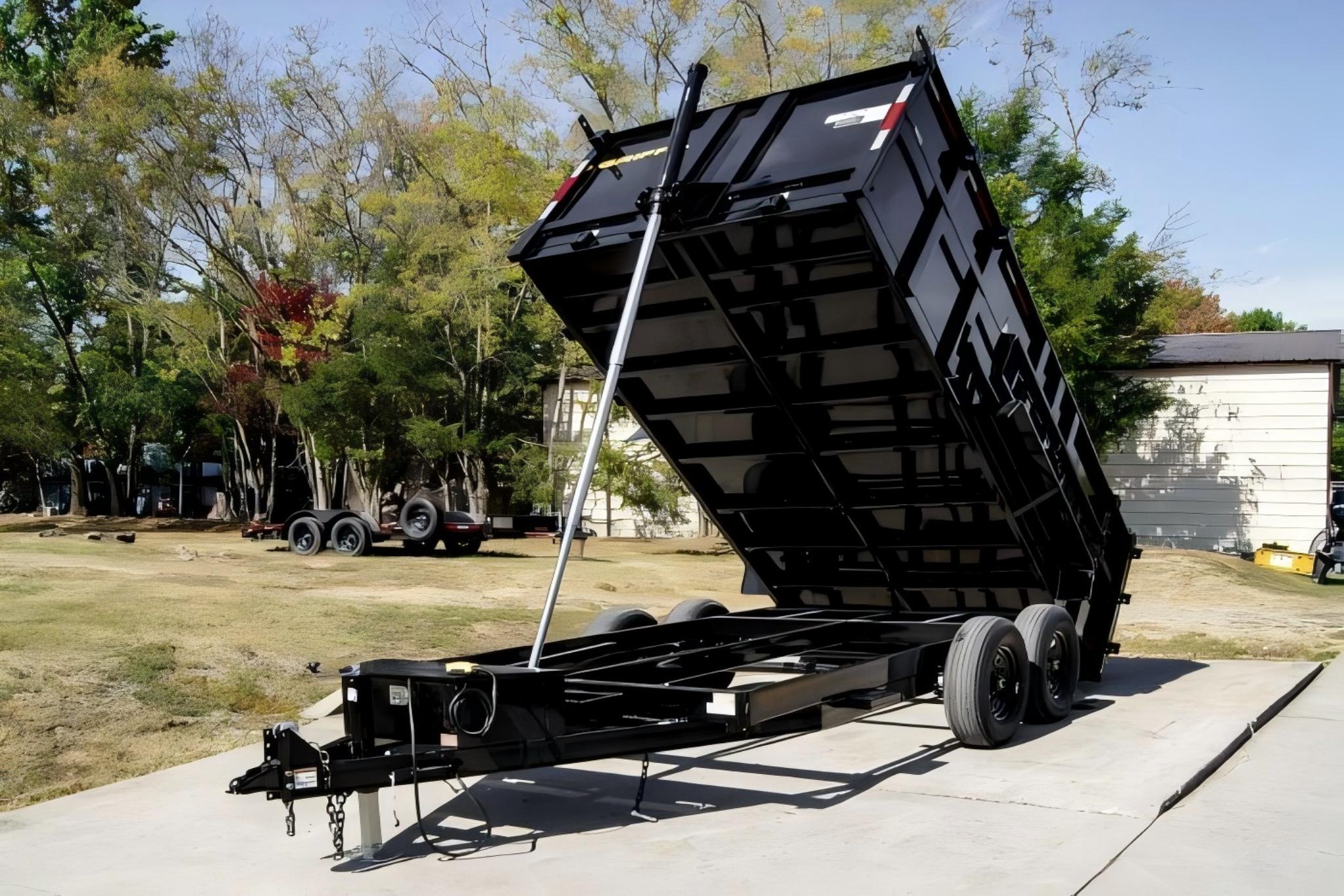
A front-mounted telescopic cylinder raises the body toward the rear hinge; retraction is by gravity and body load.
Underbody Telescopic Cylinders (L75, L90, L105 and L120 Series)
An underbody cylinder lifts the body from beneath the load floor, which suits trailers and compact tipper bodies where a front installation is not practical. The reference range covers 31 catalog models across four series with 3–6 extension stages.
Across the range, power stroke runs from 676 to 2,057 mm, maximum working pressure from 200 to 220 bar, tipping capacity from 4 to 21 tons, closed length from 367 to 598 mm, working oil volume from 2.9 to 12.1 L, and cylinder mass from 19 to 51 kg. The series split is as follows:
| Series | Stage options | Effective stage diameters | Stroke range | Max working pressure | Tipping capacity |
|---|---|---|---|---|---|
| L120 | 4 / 5 / 6 | 120 / 105 / 90 / 75 / 60 / 45 mm | 868–2,057 mm | 200 bar | 7–21 t |
| L105 | 3 / 4 / 5 / 6 | 105 / 90 / 75 / 60 / 45 / 30 mm | 816–1,872 mm | 200 bar | 5–18 t |
| L90 | 3 / 4 / 5 | 90 / 75 / 60 / 45 / 30 mm | 676–1,256 mm | 220 bar | 4–14 t |
| L75 | 3 | 75 / 60 / 45 mm | 860–1,055 mm | 220 bar | 4–9 t |
Mounting is transverse pivot or trunnion type with an induction-hardened ball upper connection and a maximum ball articulation angle of 30°, which lets the cylinder follow the body as it tips. Optional upper and lower connections use rod eyes with pins. Port options include G1/2, G3/8, M22, M18 and NPT 1/2. Operation is single-acting, with hydraulic power extension and gravity return during body lowering.
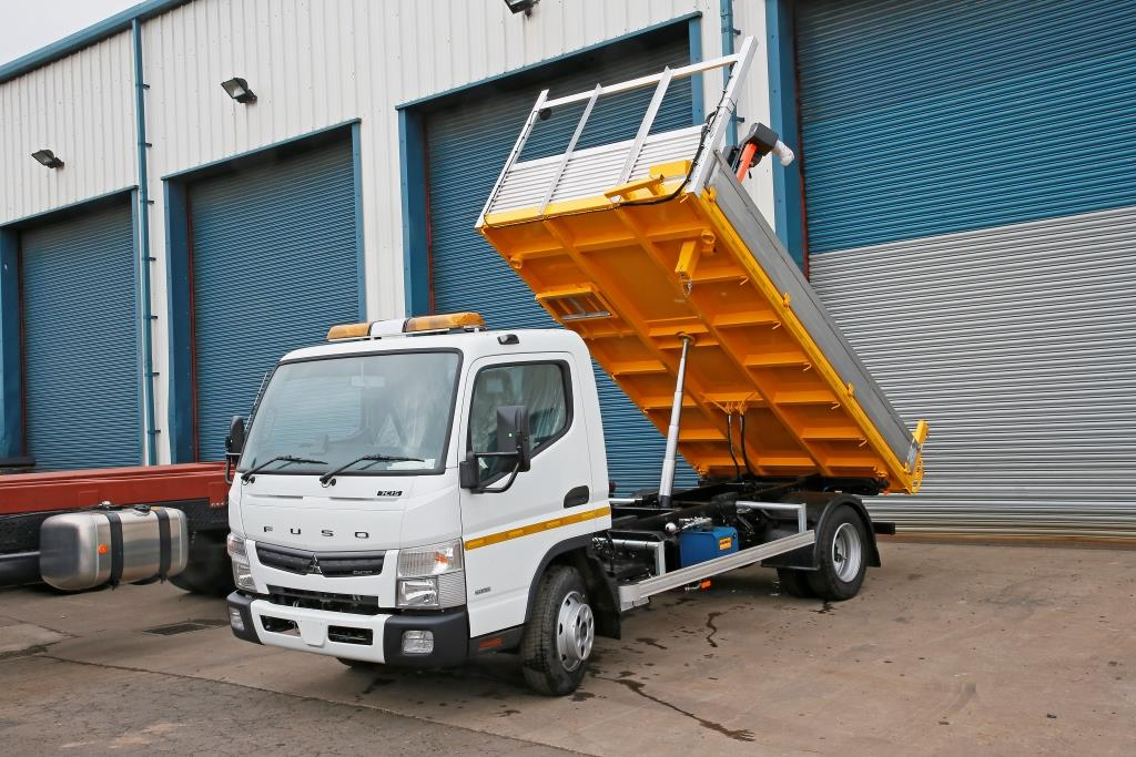
Underbody installation keeps the lifting cylinder beneath the load floor, where closed length and ball articulation drive the selection.
Inverted Front-Mount Telescopic Cylinders for Dump Trailers
The inverted configuration is installed front-mounted between the trailer frame and the dump body, with the stage stack inverted relative to a conventional front-end cylinder. The reference series covers 7-ton and 12-ton configurations at 3,000 PSI working pressure, with stroke options of 78, 90, 108, 120 and 144 inches and retracted lengths of 34.75–48.75 inches.
The final stage or rod diameter is 2.00 inches and the rod pin hole is 1.00 inch. Oil capacity ranges from 1.6 to 3.8 US gallons and product weight from 68 to 143 lbs. Port options are 1/2-inch NPT or SAE #8 ORB. Construction uses a threaded ductile-iron end cap, precision-finished telescopic stages, V-packing and a polyurethane wiper, and retraction is by gravity return. The combination of a compact retracted length and a 78–144 inch lifting stroke is the reason this configuration is specified where a conventional front-end cylinder will not fit.
Standard North American Single-Acting Telescopic Cylinders
For conventional dump trucks, single-acting telescopic cylinders are commonly built with 2–5 moving stages. The general sleeve diameter range is 1.75–14.00 inches, with standard stocking models clustering around a 5–8 inch largest stage. General stroke range is 36–500 inches, while the current stocking-model range is 72–265 inches. Nominal working pressure is 2,000 PSI (140 bar), with higher pressures subject to engineering evaluation, and the standard operating temperature range is −40°F to +200°F, approximately −40°C to +93°C.
Mounting is pin-mounted at the base and plunger end using mounting codes CC, DB, DC and MB. Port options are NPT or SAE O-ring boss depending on model, typically 1/2 inch NPT, 3/4 inch NPT, 1 inch NPT, #8 SAE, #12 SAE or #16 SAE. The largest moving stage extends first and the smallest retracts first, and the standard dump angle range is approximately 45–57 degrees. Replacement cylinders can be manufactured against a verified model number, a 10-digit part number, an approved drawing or confirmed installation dimensions.
Single-Acting Operation and the Inverted Mounting Question
Single-acting and inverted describe two different things, and buyers frequently conflate them. Single-acting describes the hydraulic function: pressure is applied in one direction only, and the cylinder returns under gravity, external load, spring force or mechanical linkage, with the minimum return load defined by seal friction, guide friction and installation orientation. In tipper duty this normally produces a simple power-up, gravity-down hydraulic circuit.
Inverted describes physical mounting orientation: the stage stack points in the opposite direction to a conventional front-end installation, which is how a front-mounted trailer cylinder combines a compact retracted length with a long lifting stroke. A cylinder can therefore be single-acting without being inverted, and the choice is settled at the mounting interface rather than in the valve circuit.
For custom telescopic designs, the number of stages, stage diameters and stage stroke distribution are engineered around total stroke, overlap and stability requirements. Stage overlap is engineered to maintain structural stability and guide support, and trunnion position is customized according to equipment geometry and tipping-force analysis. Heavier duty guides and application-specific wiper systems protect the stages in dusty, muddy and outdoor conditions, and optional load-holding protection such as counterbalance valves, pilot-operated check valves or hose-burst valves is available for lifting and load-retention duties.
Step-by-Step Sizing Workflow
- Define the tipping task. Record dump body length, rated payload, hinge position, body hinge-to-cylinder base distance, required dump angle and system working pressure. These inputs sit at the top of every selection list for dump truck and trailer cylinders, and no downstream decision can compensate for missing or approximate values.
- Choose the configuration. Front-end telescopic suits tipper trucks and tipper trailers with a clear front installation position and adequate structural support. Underbody telescopic suits trailers and compact bodies with limited front space. Inverted front-mount telescopic suits trailer applications where the cylinder must sit between frame and body while still delivering a long stroke. Scissor hoist kits become the practical alternative when body length is short: reference capacities span 3–12 tons (6,000–26,000 lbs) for recommended body lengths of 8–24 ft, using double-acting cylinders of 3.5–6.5 inch diameter, 10–30 inch stroke and 7.5–10 mm wall thickness.
- Set stroke and retracted length together. Work from the required body movement, then check the result against the available installation envelope. Total stroke and retracted length are the pair that determines fit, and stage stroke distribution is engineered around both plus overlap and stability requirements.
- Select stage count and stage diameters. Initial lifting force is calculated from the effective area of the largest stage and the working pressure. Each stage's output force is calculated separately, and the load curve is evaluated through the complete tipping cycle. More stages deliver a longer stroke from a shorter retracted length, but they also add guide, wiper and seal interfaces that must be maintained.
- Lock the mounting and interfaces. Base mounting options include trunnion, cross-tube, ball, clevis and flange; rod-end options include ball, pin-eye, clevis and spherical bearing. Confirm pin diameters, mounting widths, permitted angular movement and hose routing throughout the full stroke, and confirm port position against available hose clearance.
- Confirm the return method and hydraulic circuit. For gravity-return cylinders the circuit is power-up / gravity-down. A matching trailer power unit, for example, uses a 12 VDC motor, a 6 US quart reservoir, a maximum flow of 2.0 GPM, a 3,200 PSI relief setting at the A port and 1,500 PSI at the B port, SAE #6 ports and a two-button pendant. Where powered retraction or multiple functions are required, a double-acting mobile power unit covers 12/24/48 VDC, motor power of 0.35–3.0 kW, flow of 1.5–30 L/min, maximum working pressure of 280 bar (4,000 PSI) and reservoirs of 0.9–18 L.
- Verify flow, pressure and load holding. Calculate flow requirement from cylinder displacement and the required cycle time, then select port size to suit. Add load-holding protection where the application calls for it — counterbalance, pilot-operated check or hose-burst valves are available options, as are bleed ports matched to the installation orientation and external limit devices.
- Close the loop with documentation and testing. Manufacturing is carried out against a verified model number, part number, approved drawing or confirmed installation dimensions. Telescopic cylinders can undergo dimensional inspection, pressure testing, leakage testing, stage-sequence testing and full-stroke cycling before shipment, and replacement units can be produced from an approved drawing, a physical sample or verified installation dimensions.
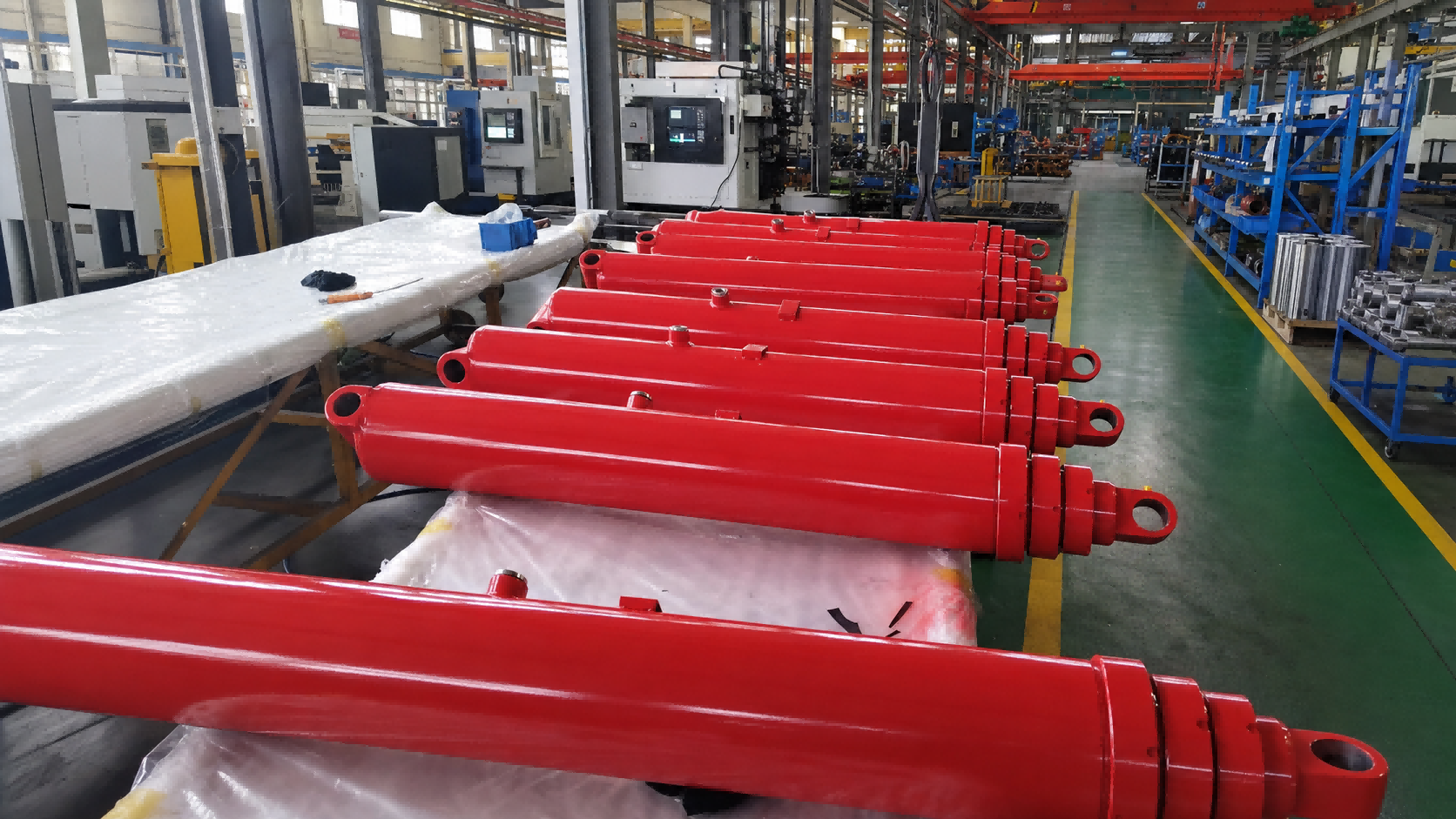
Stage-sequence and full-stroke cycling verification confirms that each telescopic stage extends and retracts in the designed order.
Where These Cylinders Are Used
Construction, quarry and aggregate tipper trucks. Front-end telescopic cylinders in the FC, FE and FEE families serve rigid tipper trucks, tipper semi-trailers, construction dump trucks, mining and quarry trucks and aggregate transport vehicles, with listed capacities from 5 to 100 metric tons and strokes up to 8,130 mm in the reference models. Typical duties include sand, gravel, aggregate, soil, ore and demolition waste, where the cylinder has to start a fully loaded body and then control the tipping angle as the load discharges.
Agricultural and compact tipping trailers. Underbody L75–L120 cylinders cover single-acting, gravity-return tipping with closed lengths of 367–598 mm and tipping capacities of 4–21 tons. The induction-hardened ball connection and 30° articulation angle allow the cylinder to track body movement as the trailer tips, and the underbody position keeps the lifting hardware clear of the trailer front. Application areas include agricultural tipping trailers, landscaping trailers, three-way tipping trailers and tractor-towed tippers.
Dump trailers with inverted front-mount cylinders. The inverted front-mount family covers 7-ton and 12-ton configurations at 3,000 PSI with 78–144 inch strokes and retracted lengths of 34.75–48.75 inches, for trailers where the frame and body leave only a narrow installation window but a long stroke is still required.
Related mobile hydraulic duties. The same sizing discipline applies elsewhere on the vehicle. Roll-off hoist cylinders are heavy-duty welded, double-acting units for cable hoist, hooklift, sliding-jib hooklift and articulating hooklift systems, with verified reference bore ranges of 3–7 inches and stroke ranges of 17–74 inches. Within those verified references, lift and dump cylinders cover 4–7 inch bore with 52.38–74 inch stroke, and jib or tilt cylinders cover 3–5 inch bore with 17–52 inch stroke; rod diameters are published at 1.5–2.5 inches where officially available. Reference system pressures for named hoist models include 1,850 PSI and 4,200 PSI, and pressure must be confirmed for each hoist model and cylinder function. Refuse truck cylinders cover packer, packing, sweep, slide, ejector, telescopic ejector, tailgate lift, hoist, fork, lift arm, grabber arm, grip, hopper and container lift functions, in single-acting or double-acting form depending on the OEM part number.
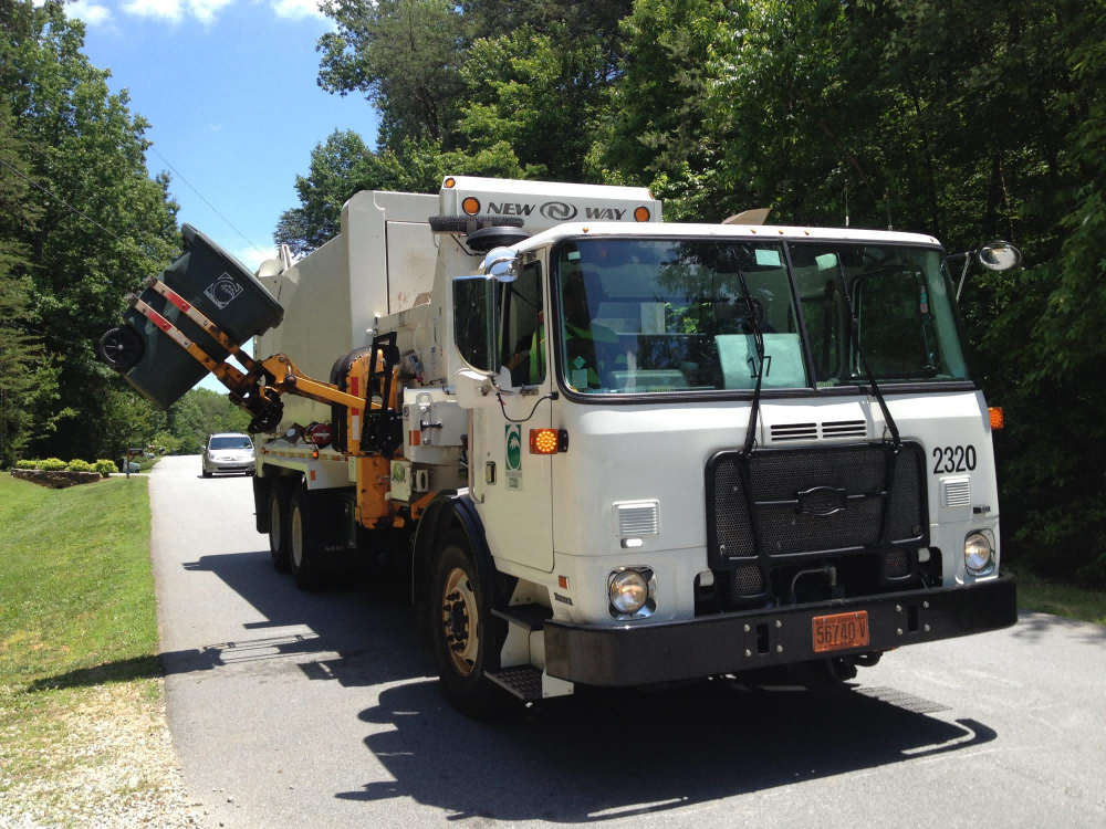
Refuse truck cylinders cover packing, sweeping, ejecting, tailgate, fork and container-handling functions under high-cycle municipal duty.
Trailer support and levelling. Hydraulic trailer jack kits rated at 12,000 lb per jack, with 20 inches of nominal travel, a 3,200 PSI maximum working pressure, a maximum flow of 2 GPM, 3/8-inch BSPP ports and a 12 VDC power supply, are a separate but related sizing exercise. They are available as single-jack or tandem-jack complete kits or as add-on kits with selector valve, and the maximum permitted distance between the ground and the bottom of the trailer frame is 8 inches.
Trademark and compatibility note: reference brand names, equipment models and part numbers — including those associated with Hyva, Parker, Galbreath, SwapLoader, Stellar, HEIL, McNeilus, New Way and Labrie equipment — are used solely to identify product compatibility. Apex Hydraulic replacement cylinders are independently manufactured products and are not represented as original parts unless expressly stated.
Configuration Comparison
| Parameter | Front-end telescopic | Underbody telescopic | Inverted front-mount telescopic |
|---|---|---|---|
| Acting type | Single acting | Single acting | Single acting |
| Return method | Gravity and tipper-body load return | Gravity return during body lowering | Gravity return |
| Installation position | Front of the tipper body | Under the dump trailer body | Front-mounted between trailer frame and dump body |
| Reference stages | 3–6 | 3–6 | Multi-stage; 7 t and 12 t configurations |
| Reference stroke | FC 3,880–8,130 mm; FE 3,880–7,130 mm | 676–2,057 mm | 78–144 in |
| Retracted length | Configured to the installation envelope | 367–598 mm closed | 34.75–48.75 in |
| Max working pressure | Up to 250 bar (typical 170–250 bar) | 200–220 bar | 3,000 PSI |
| Reference capacity | FC 33–79 t; FE 30–61 t; catalog 5–100 t | 4–21 t tipping capacity | 7 t / 12 t |
| Mounting and connection | Cover-type or trunnion (FC); eye type (FE); piston eye and bottom eye with pin (FEE) | Transverse pivot or trunnion with induction-hardened ball connection | Front-mount inverted with rod pin |
| Port options | Configured per verified model and installation | G1/2, G3/8, M22, M18, NPT 1/2 | 1/2 in NPT or SAE #8 ORB |
| Typical best fit | Tipper trucks and tipper semi-trailers with front installation space | Trailers and compact bodies with limited front space | Dump trailers needing long stroke and compact retracted length |
The ranges above are drawn from the specific product series described in this guide and are not universal limits. Final stroke, capacity, mounting position and dump angle must be confirmed against the equipment geometry, payload and hydraulic system of each individual application.
Frequently Asked Questions
Which dimensional standards apply when sizing a dump trailer or tipper truck hydraulic cylinder?
ISO 6022:2006 establishes the mounting dimensions for single rod hydraulic cylinders in the 250 bar series to ensure interchangeability, ISO 6020-2:2015 specifies mounting dimensions for the 160 bar series compact cylinders, and NFPA/T3.6.7 R3-2009 (R2024) is the North American industry standard for square head industrial cylinder mounting dimensions. Those standards govern stationary and industrial cylinder families. Mobile tipping cylinders are dimensioned around the equipment instead: retracted length is customized to the installation envelope, trunnion position is set by tipping-force analysis, and total stroke follows the required body movement. A replacement selection should therefore be confirmed against original pin-to-pin dimensions, pin diameters, mounting widths and port position.
Can a telescopic cylinder be sized to a specific stroke and tipping angle?
Yes, within the customization envelope of the telescopic design. The number of stages, stage diameters and stage stroke distribution are engineered according to total stroke, overlap and stability requirements. The largest stage extends first and retracts last, while the smallest stage retracts first. Initial lifting force is calculated from the effective area of the largest stage and the working pressure, and each remaining stage's output force is calculated separately because the load curve changes through the tipping cycle. The maximum dump or lift angle is determined by equipment geometry rather than by cylinder stroke alone, so stroke, hinge position and cylinder base position must be evaluated as one set.
What should a buyer compare instead of headline price?
Published trade data put the average export price for hydraulic cylinders and systems at approximately USD 382 per unit in 2024 (IndexBox), but that average covers very different products — a three-stage underbody cylinder and a six-stage front-end cylinder for a 100-ton tipper are not comparable purchases. Compare number of stages, largest stage diameter, stroke and retracted length, mounting type and pin sizes, port type and position, sealing and wiper specification, surface protection, and the testing documentation supplied with the unit. Because the largest stage diameter drives initial lifting force at a given pressure, it is usually the most useful comparison figure after stroke and mounting.
What information is needed before a replacement cylinder can be quoted?
The standard dump truck selection list requires the original cylinder model number, original 10-digit part number, number of stages, stroke length, closed length, base and rod-end pin diameters, mounting widths, hydraulic port size and position, dump body length, body hinge-to-cylinder base distance, rated payload, required dump angle, system working pressure, and installation photographs or a drawing. Custom long-stroke cylinders add required push and pull force, normal working load, maximum peak load, installation direction, load direction, unsupported rod length, side-load conditions, required operating speed and cycle time, hydraulic flow rate, duty cycle, operating temperature, fluid type and corrosion-protection requirement. Underbody and front-end telescopic cylinders are supplied against verified model numbers, approved drawings or confirmed installation dimensions.
Are Chinese hydraulic cylinder manufacturers suitable for dump trailer and tipper truck programs?
China is a major supply base for mobile hydraulic cylinders. Asia Pacific held a 40.5% revenue share of the global hydraulic cylinder market in 2025, led by China and India (Grand View Research), and China's hydraulic cylinder and systems exports have grown at roughly 11.5% CAGR (IndexBox). Apex Hydraulic Co., Ltd. — established in 2009 and located in Qingdao City, Shandong Province, China — operates a 50,000 m² manufacturing facility with approximately 560 staff, a 25-engineer R&D team, and annual capacity of 100,000 hydraulic cylinders and 15,000 power units. Exports account for 70% of sales across North America, Western Europe, South America, Southeast Asia, the Middle East and Australia. The sizing inputs listed above can be submitted as an approved drawing, a physical sample or verified measurements, and the engineering team can return a reviewed proposal with confirmed bore, stroke, mounting and port dimensions before production.
Send your tipping geometry — get a reviewed cylinder proposal
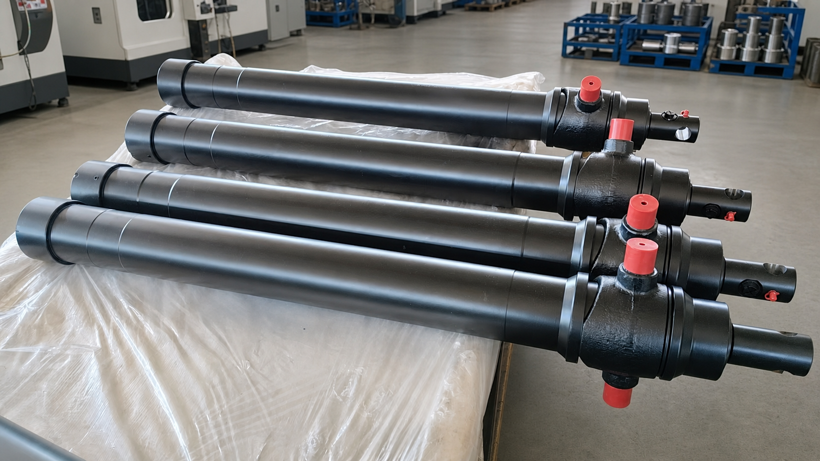
Share your body length, hinge-to-cylinder base distance, required dump angle, closed length, pin diameters, port size and position, payload and system working pressure. Apex Hydraulic can review the application, confirm the stage configuration and supply a quote or a sample unit for validation.
Download the full product catalog: APEX Hydraulic Product Catalog
Email: jason@hydraulicapex.com | Tel / WhatsApp: +86 182-5318-1828 | Website: www.hydraulicapex.com
Summary
Tipper cylinder sizing begins with geometry and ends with verification, not with a capacity figure. Front-end telescopic cylinders deliver the longest lifting strokes for conventional tipper trucks and semi-trailers; underbody telescopic cylinders fit trailers and compact bodies where front installation space is unavailable; inverted front-mount telescopic cylinders solve the trailer case where a long stroke has to come from a short retracted envelope. In all three cases the deciding inputs are the same — stroke, retracted length, stage count and diameters, mounting interface, return method, flow and port size — and the same rule applies throughout: the maximum dump angle is set by the equipment, so cylinder and body geometry must be evaluated together.
Have Questions or Need More Details?
Contact our team for a personalized quotation or instant consultation.
Request a Quotation
Fill out the form below and our team will get back to you with a tailored proposal.
WhatsApp Direct Chat
Prefer to chat in real-time? Message us on WhatsApp for instant assistance & quick answers.
- Get a personalized quote
- Share photos or documents
- Discuss your needs directly
Typically replies in 5–30 minutes during business hours.