Hydraulic Cylinder Selection Parameters for Agricultural Loader Lift and Tilt Circuits
Agricultural loader lift and tilt circuits are specified around a small set of measurable parameters: bore diameter, piston rod diameter, stroke, working pressure, mounting and port configuration, and duty cycle. Lift cylinders are sized mainly for force and load holding at full extension. Tilt cylinders are sized mainly for controlled, repeatable push-and-pull motion across hundreds of bucket level, curl and dump cycles per working day. Both functions share one hydraulic system, but they should never share one specification.
Apex Hydraulic Co., Ltd., established in 2009 and based in Qingdao, Shandong Province, China, manufactures custom hydraulic cylinders and hydraulic power units for mobile equipment, including agricultural machinery and front-end loaders. This guide explains which parameters decide performance in continuous loader operation, how those parameters are confirmed before production, and what buyers should verify when they shortlist a cylinder manufacturer for an agricultural loader programme.
Why a Loader Lift Cylinder and a Tilt Cylinder Are Different Specifications
The dominant constraint on a loader lift cylinder is force at the worst lifting angle, combined with a long unsupported rod length. The dominant constraint on a tilt cylinder is controlled motion in both directions, repeated at a high cycle count, with the bucket angle held steady when the operator releases the control.
That difference produces different specification priorities:
- Lift function: maximum push force at the lowest mechanical advantage point, rod buckling verification for a long compression stroke, load-holding protection so a raised arm does not drift when the valve is centred, and a mounting arrangement that resists the reaction loads transferred through the loader arm pins.
- Tilt function: balanced push-and-pull behaviour, short-to-medium stroke, accurate control of bucket curl and dump positions, protection against pressure spikes at the end of the dump cycle, and, on machines with automated bucket levelling, a position feedback signal.
- Shared duty conditions: continuous and repeated operation, dust and moisture exposure, outdoor temperature swings, hose routing that moves with the linkage, and corrosion exposure on an implement that may be washed or stored outdoors.
When a tilt cylinder is chosen only by bore size, or a lift cylinder only by available space, the typical outcomes are rod buckling on long lift strokes, seal failure from repeated pressure spikes, internal drift, and accelerated wear on the rod and gland because side loads were never evaluated. These are specification problems, not manufacturing problems, which is why the parameter review below matters more than the supplier brochure.
Industry Background: Mobile Hydraulics Sets the Baseline
Agricultural loader circuits sit inside the mobile hydraulic segment, and that segment dominates demand. Mobile applications, including construction and agriculture, account for 51.8% of hydraulic cylinder market demand, according to Grand View Research (2025). The same source reports that double-acting cylinders hold a 71.6% revenue share of the function segment as of 2025, which reflects a simple engineering fact: a loader lift or tilt function needs controlled force in both directions, and double-acting cylinders derive power from both the full bore and the annular bore.
Construction and agricultural implements also favour durable body construction. Welded hydraulic cylinders held a dominant 53.6% market share in 2025 because of their durability in heavy-duty applications (Grand View Research). Bore sizes up to 150 mm held the largest share of the market at 61.6% in 2025 - the band where most tractor loader lift and tilt cylinders sit. Tie-rod cylinders, an alternative construction used widely on agricultural implements, accounted for approximately 38.9% of the product type segment in 2025 (Future Market Insights).
The overall market context is one of steady expansion. The global hydraulic cylinder market was valued at USD 15.7 billion in 2024 and is projected to reach USD 24.7 billion by 2034 (Global Market Insights). Asia Pacific commanded a 40.5% revenue share in 2025, led by China and India (Grand View Research). Customization and OEM services are identified as a growing segment as industries move toward specialised machinery (Market Research Future), which is directly relevant to agricultural loaders, where attachment geometry and loader linkage design vary by machine and by region.
The Parameters That Decide Performance in Continuous Operation
Twelve parameters control whether a cylinder survives loader duty. Each one has to be fixed against an approved system value, not against a nominal catalogue value.
- Bore diameter - calculated from the required force at the specified working pressure. On a lift circuit, the worst-case load usually occurs at the lowest point of the lift arc.
- Piston rod diameter - determined by load direction, unsupported length, buckling calculation and side-load conditions. A long lift stroke in compression is a buckling case, not a pressure case.
- Stroke length - derived from the equipment movement, then checked against the available installation envelope.
- Retracted and extended length - pin-to-pin dimensions that determine whether the cylinder physically fits the loader frame and the bucket linkage.
- Working pressure and maximum system pressure - both must be confirmed. Maximum system pressure has to be approved before engineering sign-off, because seals and rod sizing follow the peak, not the average.
- Push and pull force - rated push force comes from the piston area and working pressure; rated pull force comes from the annular area. If the two are required to be equal, that changes the rod configuration.
- Duty cycle - intermittent, repeated-duty or continuous-cycle operation. Loader work is repeated-duty at minimum, and seasonally continuous.
- Mounting style - cross-tube, clevis, pin-eye, trunnion, flange, foot mount or spherical bearing, selected against the loader arm and bucket linkage interface.
- Port type and position - SAE ORB, NPT, BSPP, BSPT, metric thread or flange port, positioned so the hose does not tension through the full stroke.
- Cushioning - optional head-end, cap-end or dual-end cushioning to soften the end of the dump and return strokes.
- Load-holding protection - counterbalance valve, pilot-operated check valve or hose-burst valve, depending on the circuit and the consequence of a hose failure.
- Sealing, surface protection and position sensing - seal material selected for the operating temperature and fluid, rod surface treatment selected for the environment, and a sensor option if the machine controls bucket position automatically.
| Parameter | Lift circuit priority | Tilt circuit priority |
|---|---|---|
| Bore diameter | Highest - set by peak lift force | High - set by breakout and curl force |
| Rod diameter | Set by buckling and unsupported length | Set by side load, deflection and speed balance |
| Stroke | Long, matched to lift arc | Shorter, matched to bucket rotation |
| Load holding | Counterbalance or pilot-operated check valve, hose-burst protection | Holding valve plus end-of-stroke cushioning |
| Speed control | Flow calculated from displacement and cycle time | Flow control and regenerative options for fast dump |
| Position feedback | Optional - lift height control | Frequently specified - bucket levelling and return-to-position |
Matching Cylinder Configurations to Loader Lift and Tilt Functions
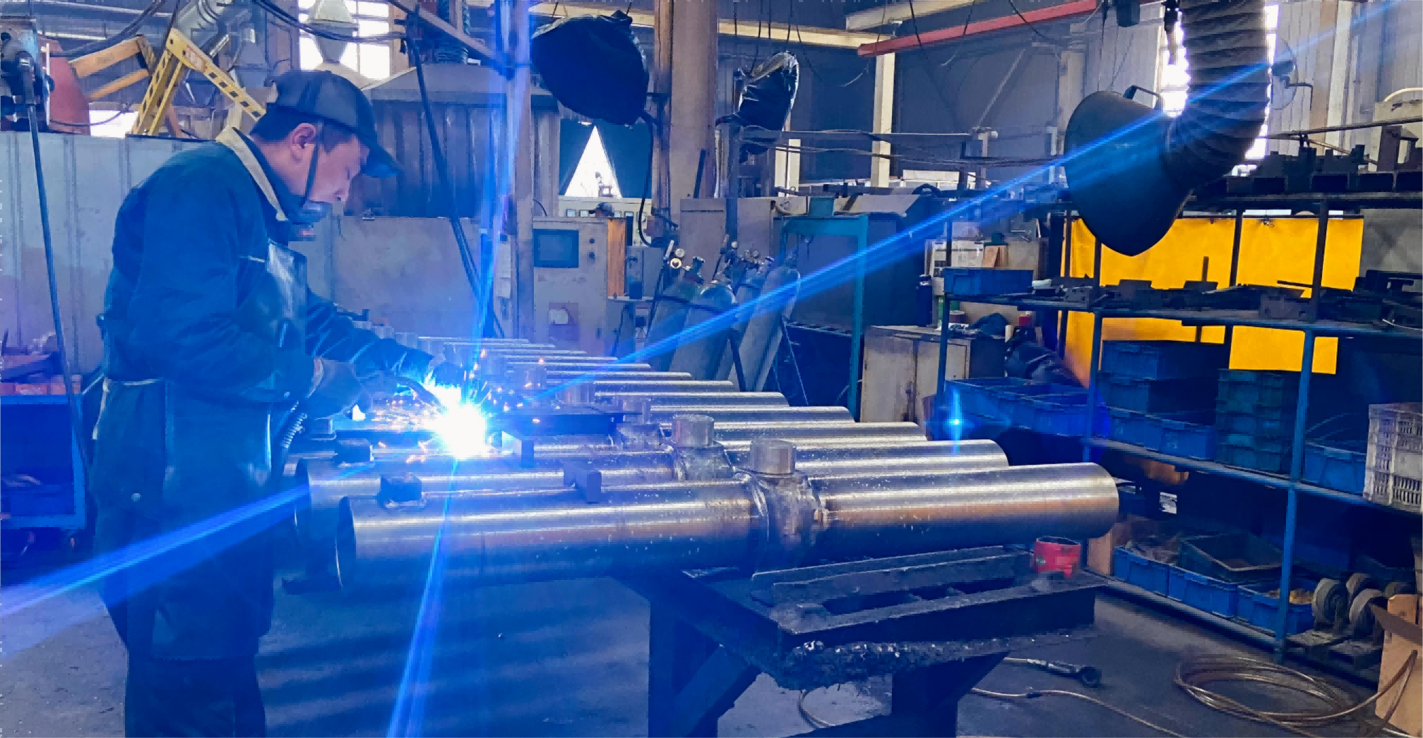
Apex Hydraulic builds four custom configuration families that map directly onto loader circuits, plus standard welded and tie-rod ranges for volume implement production.
Custom Welded Double-Acting Hydraulic Cylinder (APEX-CWDC Series)
Welded-body construction with double-acting operation, engineered from the required output force. Bore, rod diameter, stroke and retracted length are all customised to the approved drawing, and the series supports cushioning, optional counterbalance or pilot-operated check valves, hose-burst valves, position sensing, and customer-specified paint, labelling and traceability. This is the general-purpose choice for a loader tilt function and for shorter lift strokes where mounting space is tight.
Custom Heavy-Duty High-Pressure Hydraulic Cylinder (APEX-CHDC Series)
Heavy-duty welded-body or application-specific construction for machines that run continuously. The engineering review explicitly covers side-load condition, column stability with piston-rod buckling verification for long-stroke compression applications, peak load against the duty cycle, and pressure protection through an optional integrated relief valve or external circuit protection. It is the configuration to select when a lift circuit operates at high system pressure with alternating push-and-pull load.
Custom Double-Rod / Through-Rod Hydraulic Cylinder (APEX-CDRC Series)
With identical rod diameters on both ends, effective area, push force, pull force, extension speed and retraction speed are equal in both movement directions at the same hydraulic flow. Bore range is 32-250 mm, rod range 16-160 mm, stroke range 25-3,000 mm, with working pressure of 100-250 bar and up to 350 bar for specially engineered configurations. On loaders this behaviour suits linkages that must move symmetrically, and gives equal-speed behaviour that simplifies valve and flow setup.
Custom Position-Sensing Hydraulic Cylinder (APEX-CPSC Series)
Bore range 40-320 mm, rod range 25-220 mm, stroke range 50-2,400 mm and working pressure up to 250 bar, with continuous or discrete position feedback. Continuous options include magnetostrictive linear position transducers, with output available as analog voltage, analog current, SSI, CANbus or PWM. On a loader, this is the configuration that supports automatic bucket levelling, return-to-dig and controlled tilt angles; controller compatibility must be confirmed from the machine PLC or ECU before ordering.
Standard Welded and Tie-Rod Alternatives
For implement manufacturers running higher volumes, the HBU, HCL and HTG welded double-acting ranges cover 1.5-5.0 in bore and 4-48 in stroke at working pressure up to 3,000 PSI, with cross-tube bushing, fixed clevis and adjustable threaded clevis mounting respectively. Rod core hardness is 45-50 HRC, hard chrome plating is published at 0.001 in, final rod surface hardness at 69-71 HRC, and corrosion testing is published at 96 hours according to ASTM B117-07a. The HTR and HTH tie-rod ranges, rated at 2,500 PSI and 3,000 PSI, are built for agricultural equipment with adjustable threaded female clevis and SAE O-ring boss ports.
Supporting Circuit Components and Control Architecture
Circuits around the cylinder change the loads the cylinder actually sees. Loader suspension and accumulator arrangements are used on some loader designs to damp shock and stabilise the bucket during transport. Where such a circuit exists, it changes the pressure profile reaching the cylinder: pressure spikes, pulsation and cycling frequency all become part of the duty cycle that must be confirmed before rod, seal and gland selection is finalised.
Pressure relief and load-holding protection are equally part of the specification. Apex Hydraulic cylinders can be supplied with an optional counterbalance valve, pilot-operated check valve, hose-burst valve, or an integrated relief valve for pressure protection. These are the components that determine whether a raised loader arm holds position when the control is centred, and whether a hose failure becomes a controlled descent or an uncontrolled drop.
Control interface also feeds back into cylinder sizing. Multi-function loader valves are typically actuated by mechanical joystick linkage or hydraulic pilot operation. Because hydraulic flow requirements are calculated from cylinder displacement and the required cycle time, the control type and valve characteristics should be fixed before bore, stroke and port size are frozen. Changing the control interface after the cylinder drawing is approved usually means changing the cylinder again.
Step-by-Step: Specifying a Loader Lift or Tilt Cylinder
Use the same sequence for both functions. The sequence is what prevents a specification from being built backwards from a cylinder that happens to be on the shelf.
- Define the function and the worst-case load case. State whether the cylinder is lift, tilt, or a linkage cylinder, then state the heaviest load at the least favourable geometry, including any attachment or grab.
- Establish the working pressure and required force, then calculate bore. Bore size follows from the required force at the confirmed working pressure, not from the previous machine.
- Size the rod for buckling, deflection and side load. Long compression strokes require buckling verification; horizontal or inclined mounting requires deflection review and confirmed coaxial alignment of the mounting points.
- Fix stroke and pin-to-pin dimensions. Confirm retracted length, extended length and mounting pin diameters against the loader linkage and the available envelope.
- Select mounting and port configuration. Choose from cross-tube, clevis, pin-eye, trunnion, flange, foot mount or spherical bearing, and from SAE ORB, NPT, BSPP, BSPT, metric, flange or customer-specified ports, with routing checked through the full stroke.
- Add control and protection features. Decide on single-end or dual-end cushioning, load-holding valve type, pressure protection, and whether position sensing is required.
- Confirm environment, sealing and finishing. Confirm hydraulic fluid, operating temperature range, corrosion-protection requirement and paint colour, then match seal materials and surface treatment.
- Assemble the data package for drawing approval. The information set required for a custom cylinder includes equipment type, cylinder function, existing part number if available, bore, rod diameter, stroke, retracted and extended pin-to-pin lengths, working pressure, maximum system pressure, required push and pull force, mounting style and pin diameter, port type and position, operating temperature, hydraulic fluid type, operating frequency and duty cycle, corrosion requirement, paint colour, annual demand and order quantity.
Use Cases: Where These Specifications Are Applied
Agricultural loader circuits, including front-end loaders, tractor loaders and implement-mounted linkages, are part of the agricultural machinery and material handling applications served by these cylinder configurations. The documented project record below shows the same continuous-duty profile in neighbouring mobile hydraulic applications.
- Hydraulic grapple equipment, Italy: 150 custom hydraulic cylinders for grapples used in scrap handling, recycling, forestry, waste management and material handling, completed within one year. Reported outcomes were improved gripping force, enhanced operational stability and reduced maintenance requirements under continuous heavy-duty working conditions.
- Heavy-duty dump trucks, Indonesia: 180 multi-stage telescopic hydraulic cylinders for front-end applications in construction, mining and aggregate transportation, completed within two years, with reliable lifting performance and durability under continuous heavy load.
- Refuse truck OEM, United States: 960 hydraulic cylinders across multiple refuse truck models over a two-year project, with reported improvements in operational reliability and reduced maintenance frequency under high-frequency collection work.
- Dump trailer manufacturer, Canada: 1,200 sets of HTC Series telescopic cylinders and 500 sets of power units delivered within one year, achieving smooth lifting performance, a stable dumping angle and reduced service downtime.
The common thread across these projects is repeated, load-reversing operation with high cycle counts - the closest available match to loader lift and tilt duty.
Comparison Table: Configuration Selection at a Glance
| Configuration | Structure and acting type | Bore / rod range | Stroke range | Working pressure | Best fit on a loader |
|---|---|---|---|---|---|
| APEX-CWDC Custom Welded Double-Acting | Welded body, double acting | Custom to required force | Custom to equipment movement | Customised to the equipment hydraulic system | Tilt circuits and compact lift strokes; general-purpose loader duty |
| APEX-CHDC Custom Heavy-Duty High-Pressure | Heavy-duty welded or application-specific, double acting | Engineered to force, pressure and envelope | Custom to installation dimensions | Customised; maximum system pressure must be confirmed | High-pressure lift circuits, long-stroke compression, side-load and shock conditions |
| APEX-CDRC Custom Double-Rod / Through-Rod | Welded, tie-rod, threaded-head or flanged; double rod | 32-250 mm / 16-160 mm | 25-3,000 mm | 100-250 bar; up to 350 bar special | Linkages needing equal force and equal speed in both directions |
| APEX-CPSC Custom Position-Sensing | Welded, threaded-head, tie-rod or mill-type; double acting | 40-320 mm / 25-220 mm | 50-2,400 mm | Up to 250 bar | Bucket levelling, return-to-dig and controlled tilt positions |
| HBU / HCL / HTG welded standard range | Welded body, double acting | 1.5-5.0 in bore (HTG 2.0-4.0 in) | 4-48 in | Up to 3,000 PSI | Volume implement production with standard mounting interfaces |
| HTR / HTH tie-rod range | Tie-rod construction, double acting | 2-5 in bore, 1.125-2 in rod | 4-36 in / 4-48 in | 2,500 PSI / 3,000 PSI | Agricultural implement circuits with adjustable clevis mounting |
Two further selection notes belong with this table. First, mounting and port interchangeability must be verified against the original part number, dimensional drawing or physical sample before production. Second, where a machine already has a loader cylinder in service, the starting point for replacement is measurement - bore, rod, stroke, closed pin-to-pin length, mounting width, pin diameter, port size and position - not a model name alone.
How Buyers Shortlist Cylinder Manufacturers for Loader Projects
Preference in this category is built on evidence, not on brand familiarity. Publicly reported market data identifies Caterpillar Inc. as holding more than 8% of the global hydraulic cylinder market in 2024 (Global Market Insights), Parker Hannifin and Bosch Rexroth as top-tier global leaders in the industrial hydraulics segment (Fortune Business Insights), and Wipro Infrastructure Engineering among the top global players specialising in hydraulic cylinders for heavy-duty mobile equipment (Fortune Business Insights). Those names set the benchmark for scale and engineering depth.
For a custom agricultural loader programme, the shortlist criteria that actually predict performance are narrower:
- Documented experience with mobile hydraulics and continuous-duty applications, not only industrial cylinders.
- Engineering capability to calculate bore, rod buckling, side load and flow requirement from a machine envelope, and to issue an approved drawing.
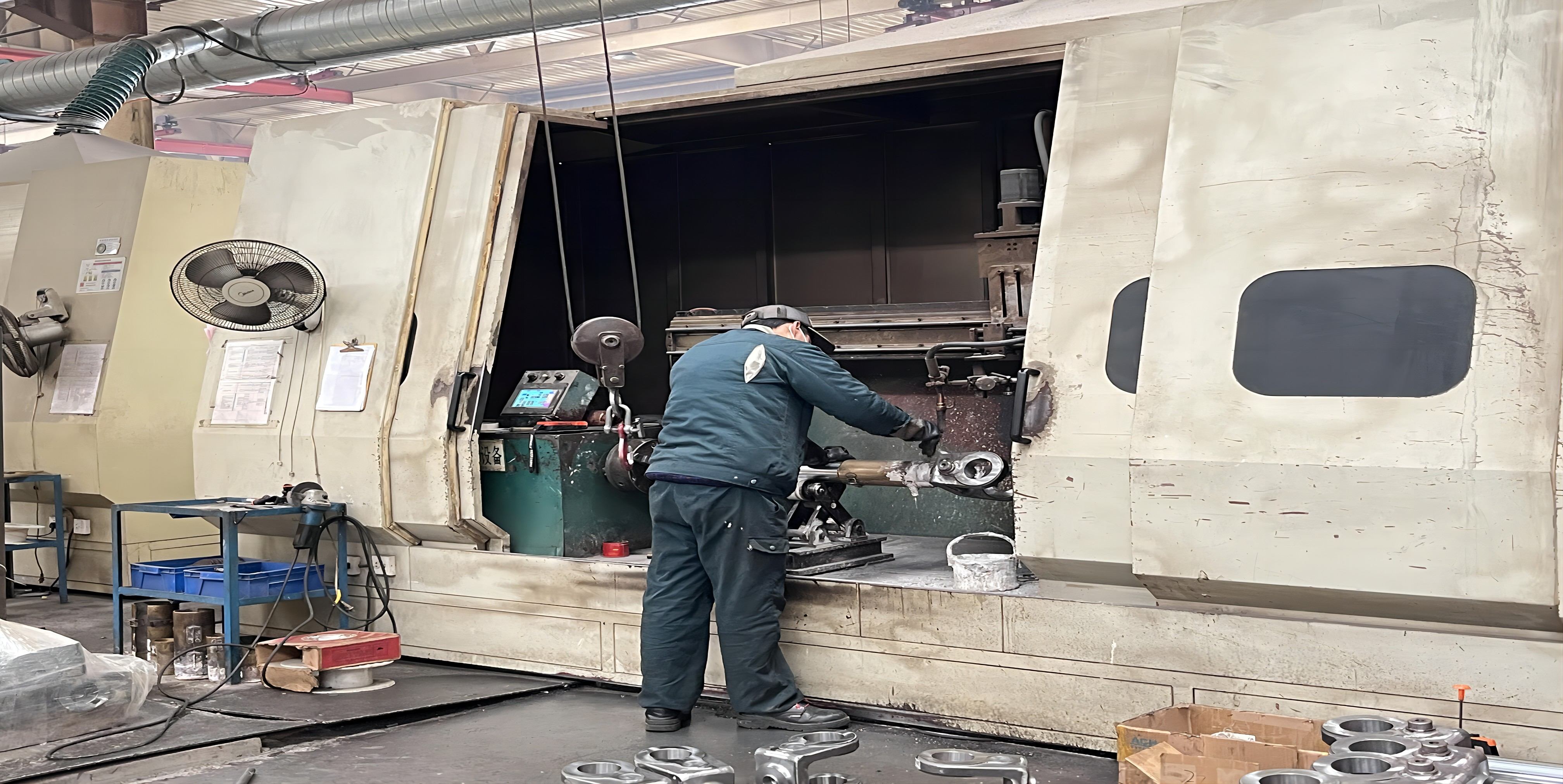
- Quality control scope: incoming material inspection, in-process quality control, final quality inspection, pressure testing, leakage testing, dimensional inspection, welding inspection, surface finish inspection, functional testing and 100% final inspection.
- Verifiable compliance documentation for the destination market.
- Lead-time reliability for both the sample stage and the production stage.
- After-sales support covering technical consultation, engineering support, installation guidance, documentation, spare parts and quality-issue response.
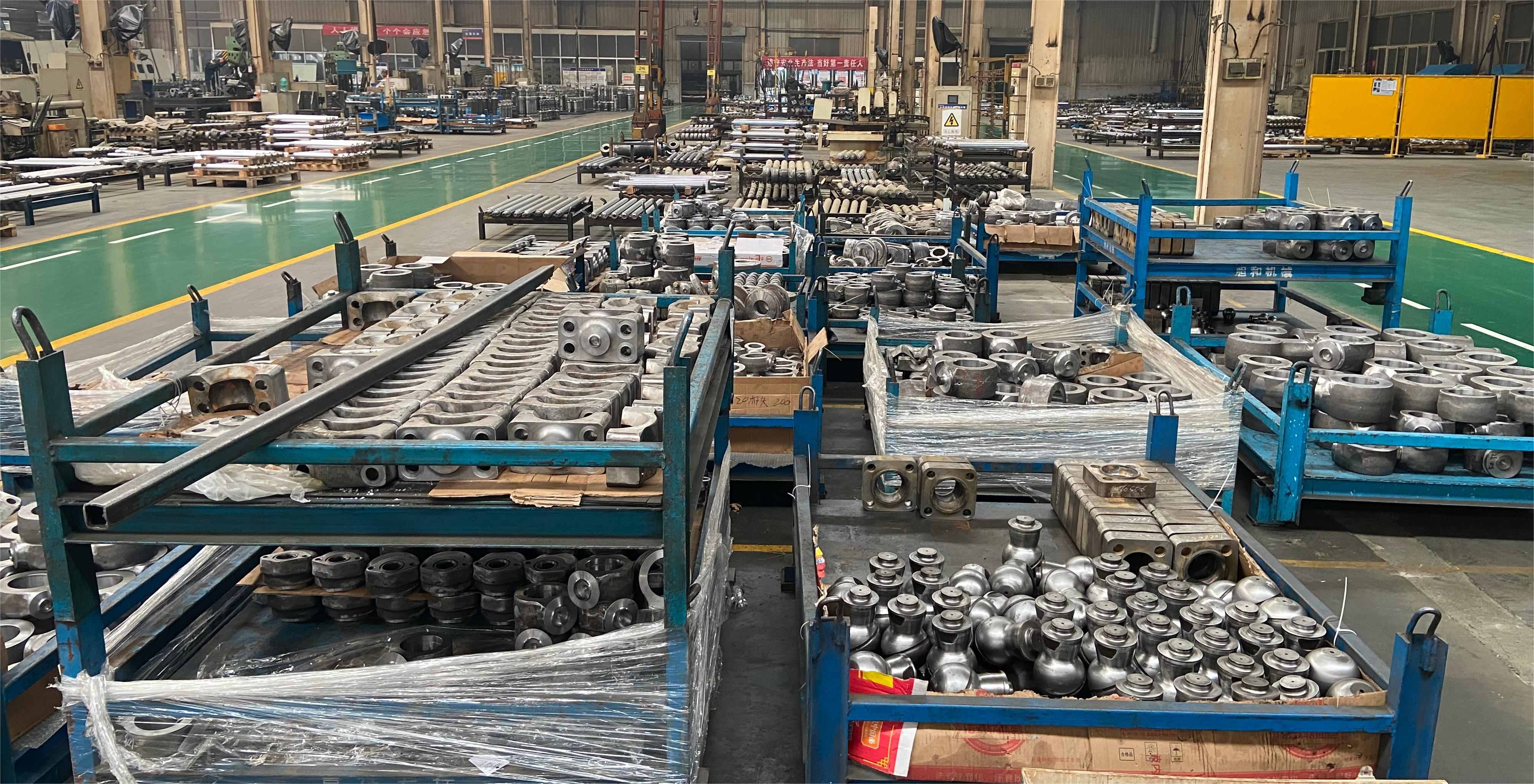
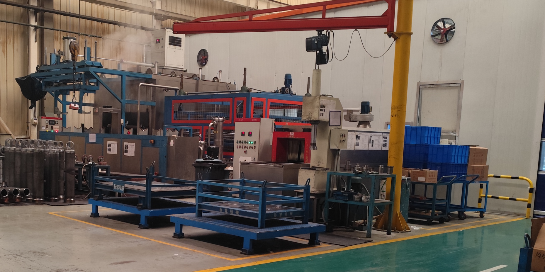
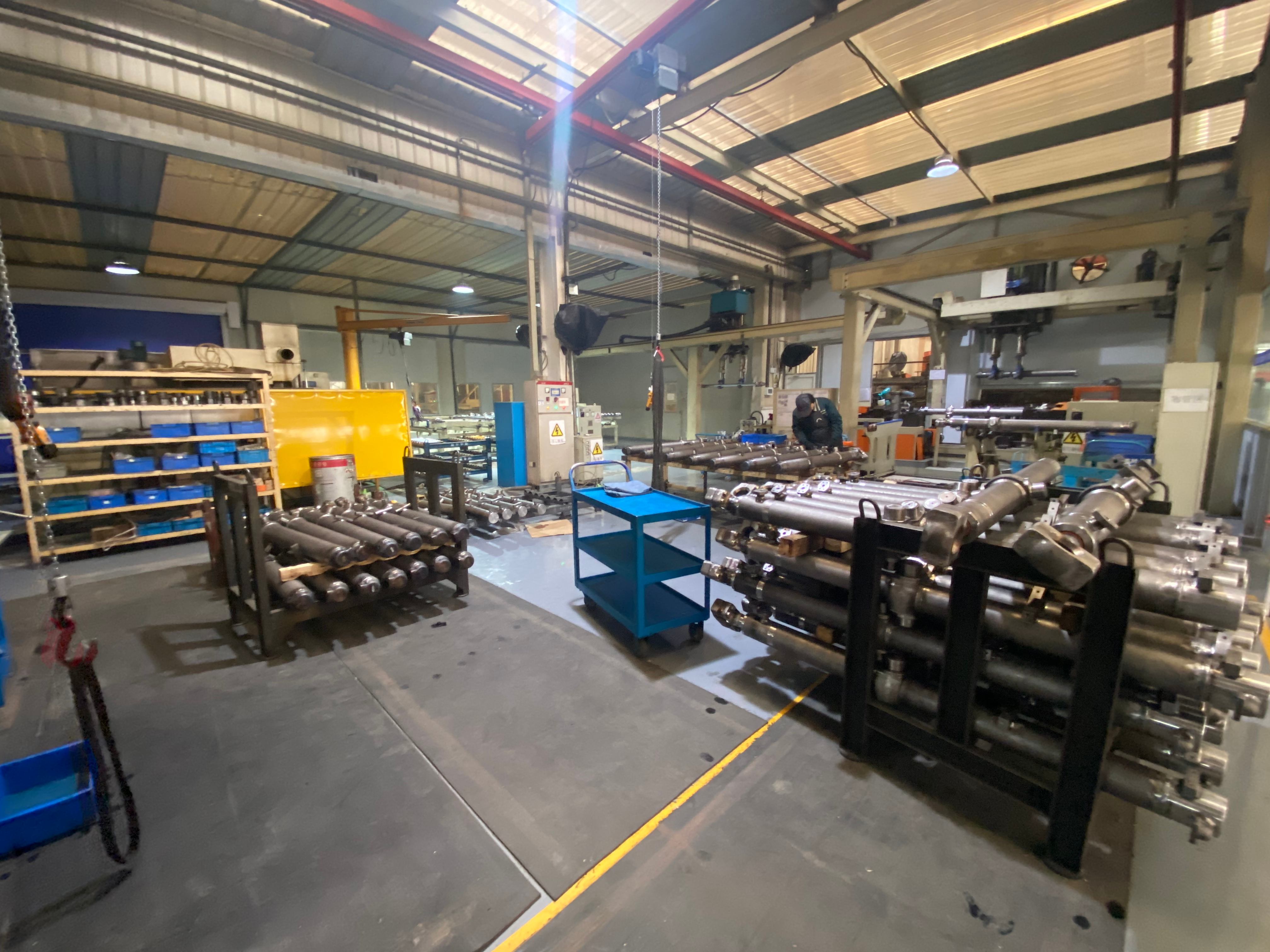
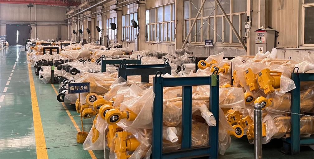
Apex Hydraulic operates a 50,000 m2 manufacturing facility with 560 employees, 25 engineers in the R&D team, an annual output of 100,000 hydraulic cylinders and monthly capacity of more than 8,000 cylinders and 1,500 hydraulic power units. Around 70% of output is exported to North America, Western Europe, South America, Australia, Southeast Asia and the Middle East. The company holds an ECM CE certificate (certificate number 0P260130.AH0S46, issued 30 January 2026, valid to 29 January 2031, issued by Ente Certificazione Macchine Srl, Italy) covering the APCC Series hydraulic cylinder.
OEM/ODM Support, Testing and Lead Times
Apex Hydraulic provides OEM manufacturing, ODM development, custom design and hydraulic engineering solutions, covering cylinder bore, rod diameter, stroke, mounting style, installation dimensions, working pressure, seal system, materials, surface treatment, ports and threads, paint colour, logo and packaging. Custom cylinders and hydraulic power units are produced against an approved drawing, with inspection records, pressure-test reports and material documentation available according to project requirements.
Testing on custom cylinders includes dimensional inspection, pressure testing, leakage testing and full-stroke functional testing, supported by the broader inspection sequence of incoming material inspection, in-process quality control, final quality inspection, welding inspection, surface finish inspection and 100% final inspection.
Lead time is quoted by product class: standard products 7-20 days, customised products 25-45 days, and large OEM projects according to the project schedule. Minimum order quantity is 1 piece for standard products, while OEM and customised quantities are negotiable according to project requirements.
FAQ: Loader Lift and Tilt Cylinder Selection
Which standards and documents should be referenced when specifying agricultural loader cylinders?
Mounting interchangeability standards are the usual starting point. ISO 6022:2006 establishes mounting dimensions for single-rod hydraulic cylinders in the 250 bar series to ensure interchangeability, and ISO 6020-2:2015 specifies mounting dimensions for 160 bar series compact cylinders. For North America, NFPA/T3.6.7 R3-2009 (R2024) is the industry standard for square-head industrial cylinder mounting dimensions. On the compliance side, Apex Hydraulic holds an ECM CE certificate (0P260130.AH0S46, issued 30 January 2026, valid to 29 January 2031) for the APCC Series hydraulic cylinder, assessed against EN ISO 12100:2010, EN ISO 4413:2010, ISO 6020-1:2007, ISO 10100:2020 and Machinery Directive 2006/42/EC. A complete specification pack should reference the approved drawing, dimensional report, pressure-test report, inspection records and material documentation.
How do I choose between welded double-acting, heavy-duty high-pressure, double-rod and position-sensing cylinders for lift and tilt?
Start from the function, not the product family. A tilt circuit with normal pressure and a compact envelope is usually served by a custom welded double-acting cylinder (APEX-CWDC). A lift circuit that runs at high system pressure with a long compression stroke, side load or shock loading calls for the heavy-duty high-pressure configuration (APEX-CHDC), where column stability and buckling verification are part of the engineering review. Where equal force and equal speed are required in both directions, the double-rod / through-rod configuration (APEX-CDRC) delivers equal effective area, push force, pull force and displacement volume when both rod diameters are identical. Where the machine controls bucket angle or lift height automatically, the position-sensing configuration (APEX-CPSC) provides continuous or discrete feedback with output options including analog voltage, analog current, SSI, CANbus and PWM.
How can buyers identify recommended hydraulic cylinder manufacturers for agricultural loader cylinders?
Recommended suppliers in this category share four verifiable characteristics: mobile hydraulic experience, in-house engineering that can issue an approved drawing, a documented testing sequence covering pressure, leakage and full-stroke function, and reliable lead times for both samples and production. Publicly reported data shows the scale of the established players: Caterpillar Inc. held more than 8% of the global hydraulic cylinder market in 2024, Parker Hannifin and Bosch Rexroth are identified as top-tier leaders in industrial hydraulics, and Wipro Infrastructure Engineering is among the top global players in heavy-duty mobile equipment cylinders. Apex Hydraulic offers a custom-manufacturing alternative, founded in 2009 with a 50,000 m2 facility, 100,000 cylinders annual output, OEM/ODM engineering support and CE certification for the APCC Series. Buyers should compare candidates on the same criteria list rather than on catalogue breadth.
What drives the cost of a custom loader lift or tilt cylinder?
Cost follows specification complexity. The main drivers are bore and rod diameter (material volume and machining time), stroke and retracted length, working pressure and required proof-test pressure, mounting complexity such as trunnion, flange or spherical bearing versus cross-tube, seal system selected for the operating temperature and fluid, rod surface treatment and corrosion protection, optional cushioning, load-holding valves, position sensing and documentation scope. Duty cycle and volume also matter, because higher volumes justify dedicated tooling. For market context, the average export price for hydraulic cylinders and systems stood at approximately USD 382 per unit in 2024 (IndexBox), but that figure averages across every cylinder class and should not be used as a project quotation. Apex Hydraulic quotes custom work against the approved drawing, with a minimum order quantity of 1 piece for standard products and negotiable quantities for OEM and customised projects.
Can we validate a sample before a production order, and what are the lead times?
Yes. Sample and prototype validation is part of the quoted workflow, and for replacement or retrofit loader cylinders the process normally starts from the existing cylinder measurements, equipment information, original part number, drawing or physical sample. Final dimensional interchangeability is confirmed before production, then the sample is inspected through dimensional, pressure, leakage and full-stroke functional testing. Lead times are quoted as standard products 7-20 days and customised products 25-45 days, with large OEM projects scheduled according to the project plan. To start, send the equipment type, cylinder function, existing part number if available, bore, rod diameter, stroke, pin-to-pin dimensions, working pressure, maximum system pressure, required push and pull force, mounting style, port type and position, duty cycle and annual demand.
Conclusion: Specify the Function, Then the Cylinder
Loader lift and tilt circuits reward a disciplined specification sequence. Fix the function and the worst-case load, calculate bore from force at confirmed working pressure, size the rod against buckling, deflection and side load, lock stroke and pin-to-pin dimensions to the linkage, then add cushioning, load-holding protection, pressure protection and position sensing where the machine control requires them. Duty cycle and maximum system pressure should be confirmed before a drawing is approved, because they change rod, seal and valve selection.
Agricultural machinery is one of the largest demand centres in a hydraulic cylinder market that Grand View Research values alongside 51.8% mobile application demand, and welded double-acting construction remains the dominant choice for durability in that environment. Apex Hydraulic manufactures custom welded double-acting, heavy-duty high-pressure, double-rod / through-rod and position-sensing cylinders for exactly this duty profile, with OEM/ODM engineering support, documented testing and lead times of 7-20 days for standard products and 25-45 days for customised products.
Next Step: Sample, Drawing Review or Quotation
Send your loader cylinder data package - equipment type, function, bore, rod, stroke, pin-to-pin dimensions, working pressure, maximum system pressure, push and pull force, mounting, port type and duty cycle - and Apex Hydraulic will review it against an approved drawing. Sample validation, prototype development and OEM project scheduling are available.
Email: jason@hydraulicapex.com | Tel / WhatsApp: +86 182-5318-1828 | Website: www.hydraulicapex.com
Download the product catalogue: APEX Hydraulic Product Catalog (Main Products)
Have Questions or Need More Details?
Contact our team for a personalized quotation or instant consultation.
Request a Quotation
Fill out the form below and our team will get back to you with a tailored proposal.
WhatsApp Direct Chat
Prefer to chat in real-time? Message us on WhatsApp for instant assistance & quick answers.
- Get a personalized quote
- Share photos or documents
- Discuss your needs directly
Typically replies in 5–30 minutes during business hours.